MERRYTEK JOURNAL / ENGINEERING INSIGHTS
Understand sensing.
Control every beam of light.
From sensing principles to field commissioning.
Clear technical evidence for every lighting-engineering decision.
TECHNOLOGY WORTH EXPLORING
Start with the right question.
System boundaries behind every protocol,
and engineering judgement beyond each parameter.
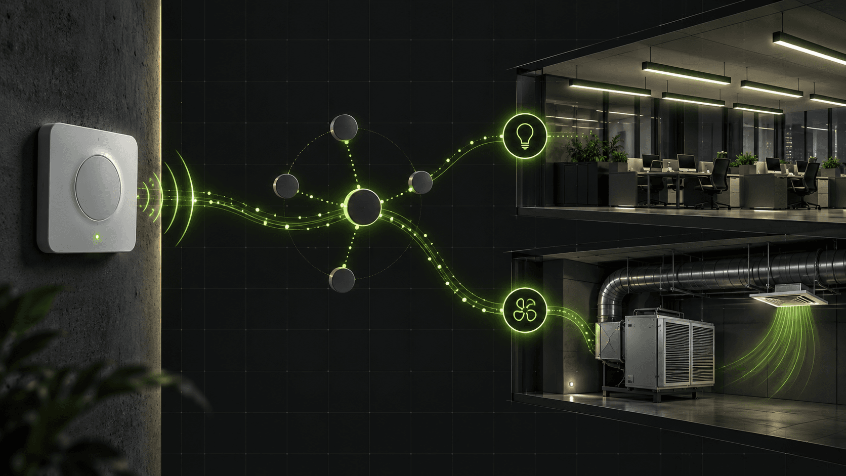
Bluetooth NLC and HVAC Integration: Taking Occupancy Data Beyond the Luminaire
A practical guide to occupancy data, wireless interoperability, and the ecosystem checks needed before connecting lighting information to HVAC.
Read article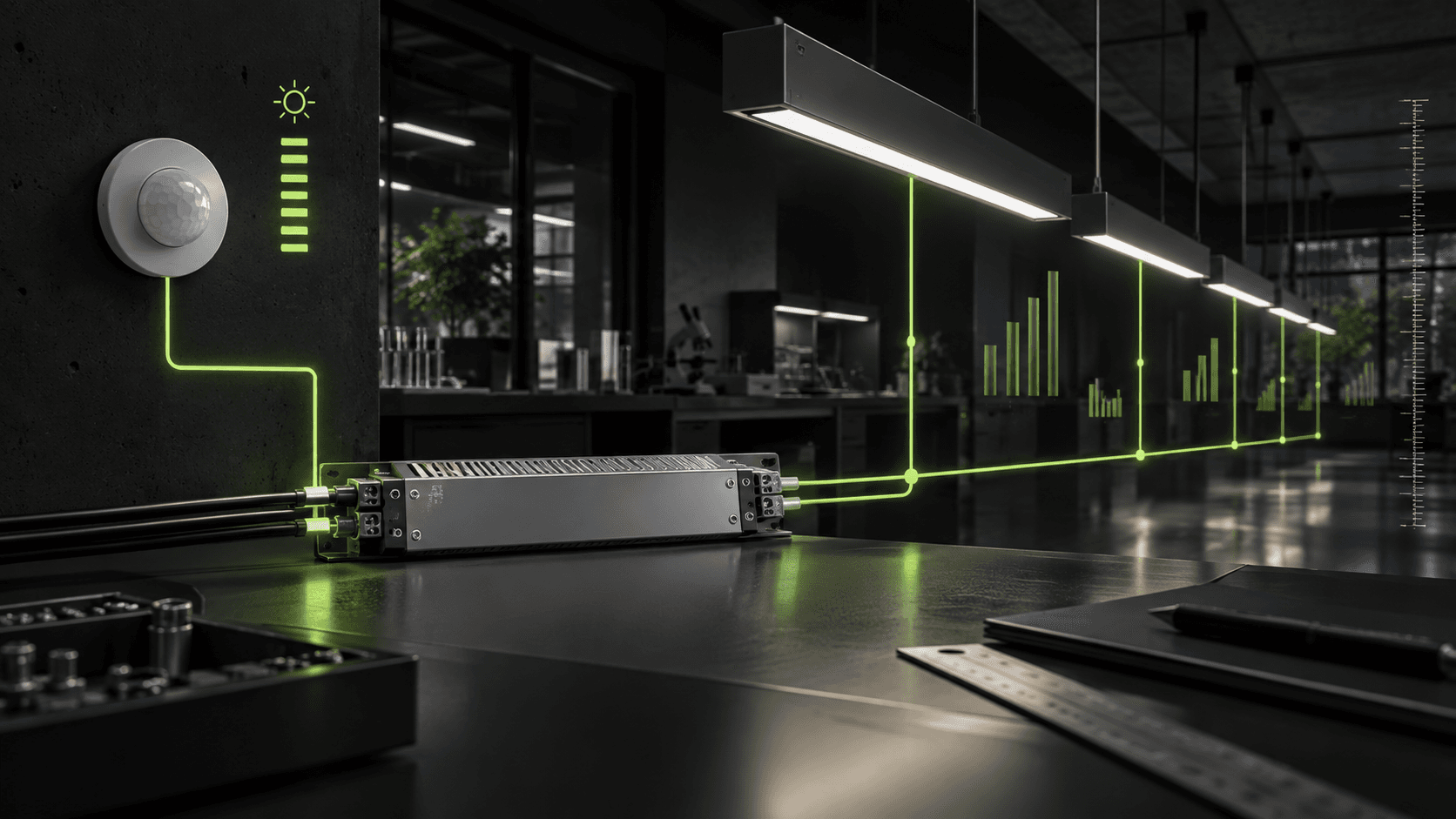
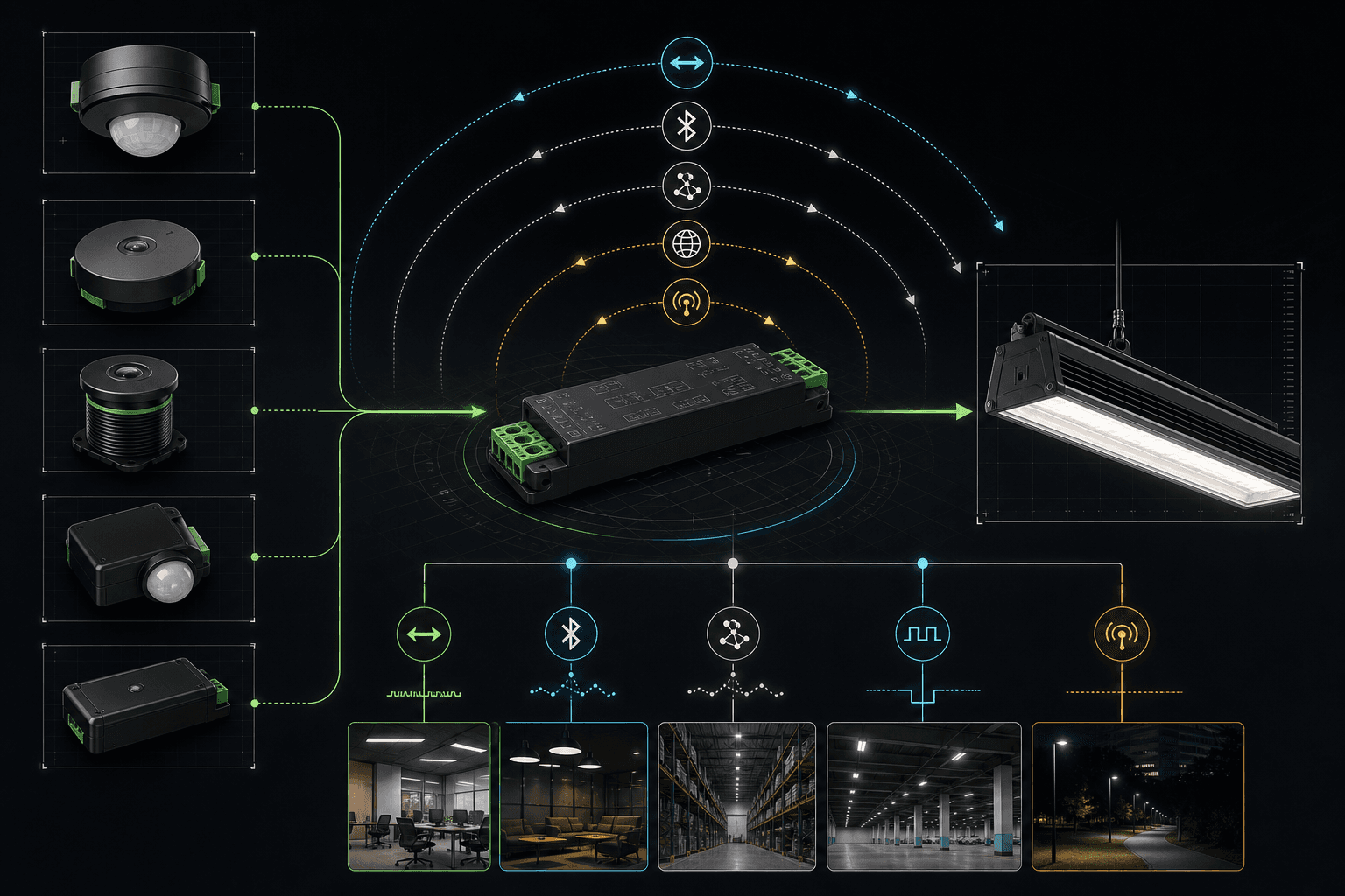
DALI Driver Selection: From Interface to Verified Lighting Behavior
Read article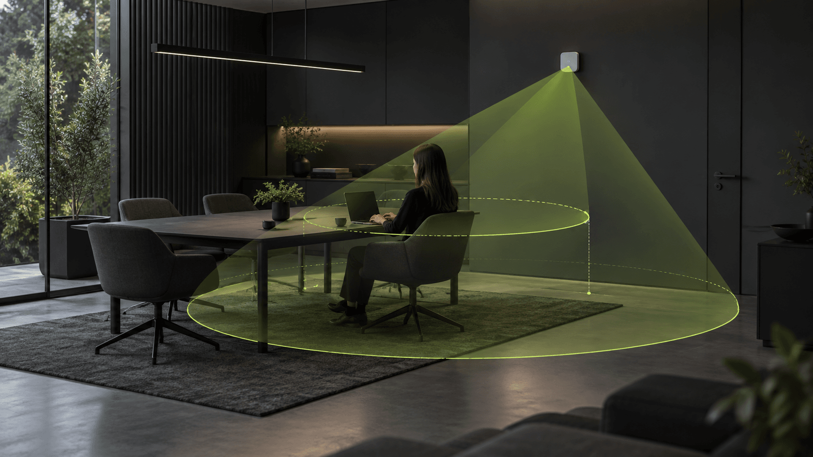
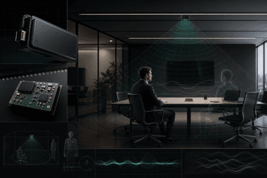
24GHz Presence Sensing: Why Motion Detection Is Not the Same as Staying Present
Read articleENGINEERING LIBRARY
Make every question clear.
Ten long-form technical articles,
connecting principles, parameters, and applications.
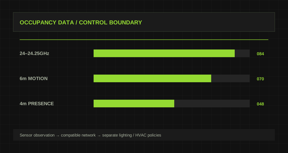
Bluetooth NLC and HVAC Integration: Taking Occupancy Data Beyond the Luminaire
A practical guide to occupancy data, wireless interoperability, and the ecosystem checks needed before connecting lighting information to HVAC.
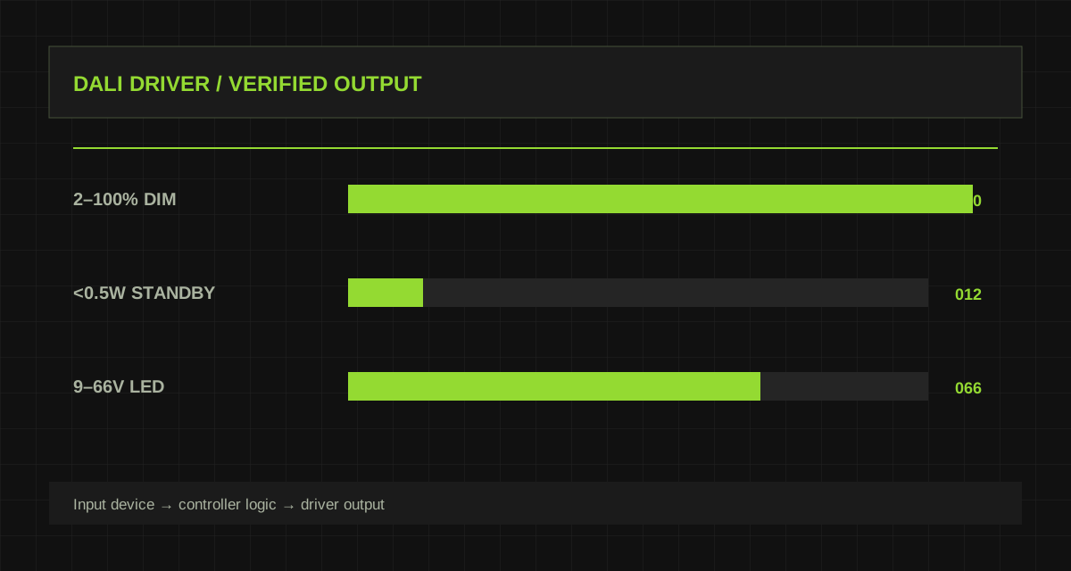
DALI Driver Selection: From Interface to Verified Lighting Behavior
Use real KL70C and KL60C parameters to separate driver selection, DALI capability, power limits, and field acceptance.
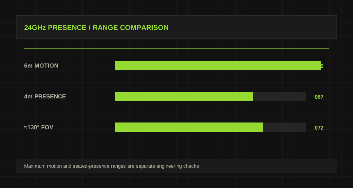
24GHz Presence Sensing: Why Motion Detection Is Not the Same as Staying Present
M3 lists 6m motion detection and 4m presence detection. Learn how to plan quiet-seat coverage and verify real operating conditions.
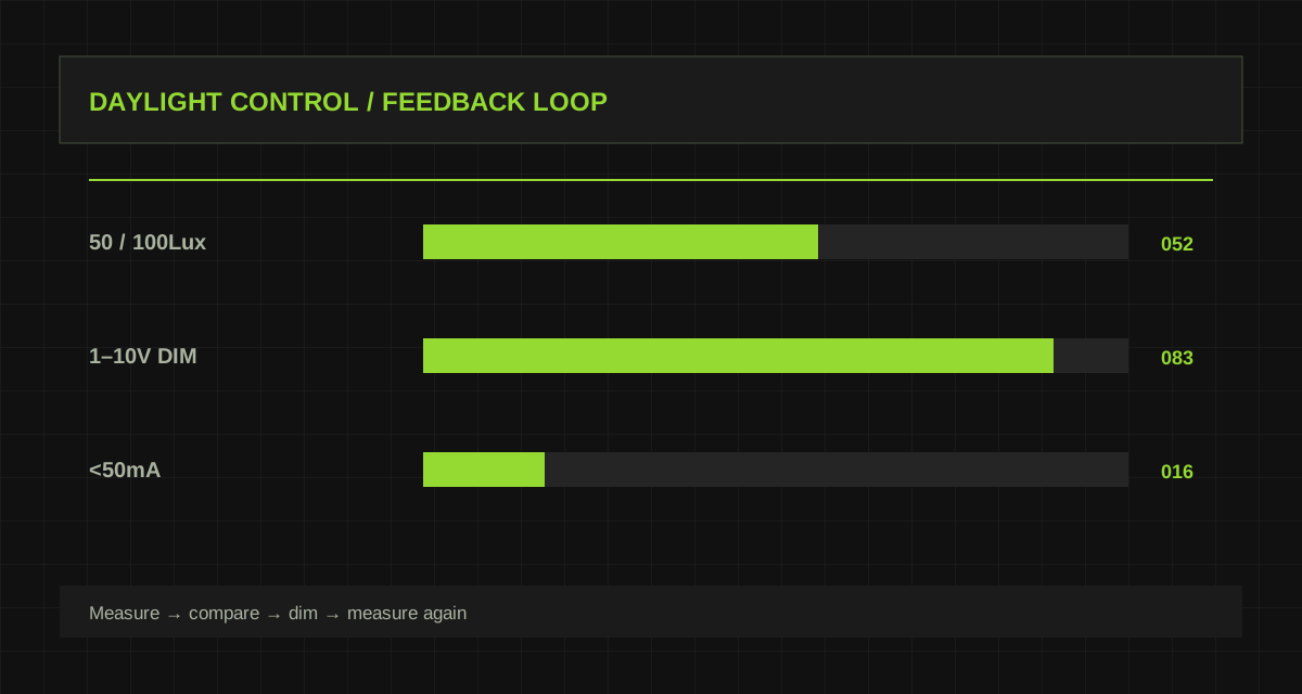
Daylight Harvesting Control: Let Daylight Participate Without Repeated Switching
Compare MS02 threshold switching with MS10 constant-light dimming, then plan sensor placement, calibration, and stable behavior.
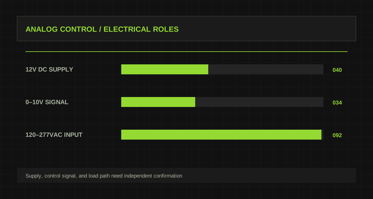
0–10V and 1–10V: Details to Verify Before Connecting a Lighting Controller
Separate device power, analog dimming signal, and switching path before mixing sensors and LED drivers on a control circuit.
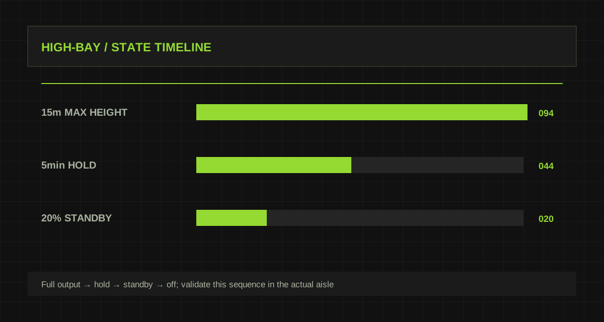
High-Bay Sensor Commissioning: Design for Mounting Height, Racking, and Standby Behavior
Use MC079D RC3 and MC054 RC4 parameters to turn high-bay sensing into an observable, repeatable warehouse control strategy.
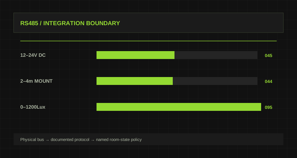
Integrating an RS485 Lighting Sensor with Building Control: Confirm the Protocol Before the Automation
MSA237D 99 485 provides an RS485 output. Learn how to distinguish physical bus, application protocol, data mapping, and safe fallback behavior.
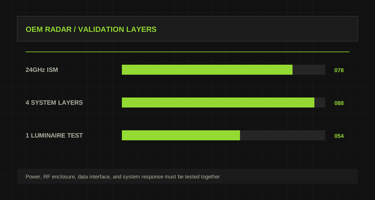
Radar Module Integration: From a 24GHz PCB to Reliable Luminaire Sensing
Use MIC08-24GE as a starting point for an OEM validation plan covering RF enclosure effects, power integrity, interfaces, and production traceability.
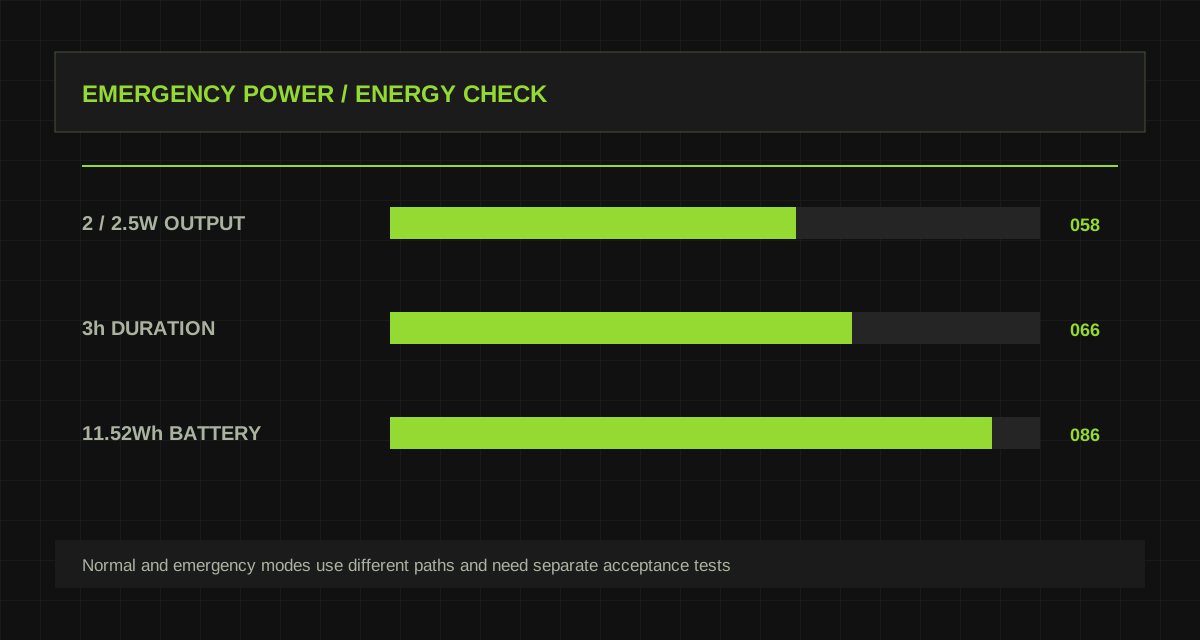
Emergency Lighting Power: Start with KE026 Power, Battery, and Output Range
Use KE026 parameters to check variant selection, LED load, charging conditions, changeover behavior, and maintenance evidence.
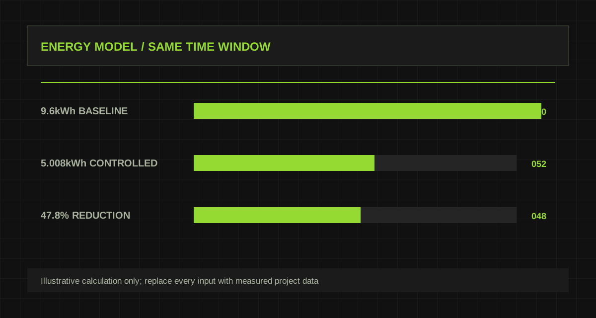
How to Measure Lighting-Control Savings: From Standby Power to a Reproducible Result
Build an energy model from measured input power, operating states, standby boundaries, and user experience rather than an untraceable savings percentage.
PUT KNOWLEDGE TO WORK