Responsive daylight control is a measured feedback process, not simply “daylight on, lighting off.” Recent connected-lighting work makes the case for collecting better information at the point of use, but engineering value appears only when the information survives the path from device to decision to actual luminaire behavior. That path needs a defined installation context, a named control owner, and a record of what each component is known to do.
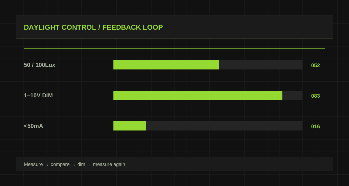
This article uses the current product record as a practical starting point. MS02 is an ON/OFF controller with paired daylight thresholds such as 50/100Lux. MS10 is listed as a 1–10V constant-light daylight-harvesting controller, with less than 50mA working current and IP20 protection. The selection method is deliberately conservative: use published parameters to constrain a design, and use documented integration information plus site testing to validate every behavior that is not explicitly stated.
The engineering method is discussed against real models. Diagrammed examples and conceptual connections name their operating boundaries. Confirm product parameters against the current model, variant, and applicable technical documentation.
Why daylight control needs more than a threshold
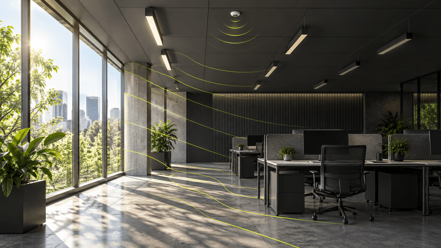
Responsive daylight control is a measured feedback process, not simply “daylight on, lighting off.” A project should begin with the operational question rather than a feature name. Identify the people, equipment, light level, response time, and maintenance outcome that the space needs. This makes it possible to distinguish a useful requirement from a marketing label.
Threshold switching and continuous constant-light control are different strategies. A sensor reading is also not automatically the same as the illuminance at a desk or task plane. Treat this distinction as a design input. It prevents a system diagram from assigning responsibilities to a product before its actual interface, documented function, and configuration route have been verified.
Keep the evidence attached to the decision that it supports. Record the model and variant, physical location, configuration revision, wiring or network condition, date, observer, measured result, and any exception. When a result changes after a setting, installation, or firmware change, preserve both records. This gives the next engineer a way to distinguish a changed requirement from a changed system response.
Distinguish MS02 switching from MS10 dimming
MS02 is an ON/OFF controller with paired daylight thresholds such as 50/100Lux. MS10 is listed as a 1–10V constant-light daylight-harvesting controller, with less than 50mA working current and IP20 protection. Read each field together with its condition and unit. A current setting, voltage window, maximum mounting height, standby figure, or IP rating has meaning only in the context of the specific product variant and installed assembly.
Create a short “known / confirm / test” table for the project. Published data belongs in known; exact firmware, wiring, protocol, mounting construction, load, and operating condition belong in confirm or test until evidence moves them into the known column.
Keep the evidence attached to the decision that it supports. Record the model and variant, physical location, configuration revision, wiring or network condition, date, observer, measured result, and any exception. When a result changes after a setting, installation, or firmware change, preserve both records. This gives the next engineer a way to distinguish a changed requirement from a changed system response.
Choose a location that represents the control zone
Define control zones first, keep window and interior zones separate where their daylight behavior differs, then establish the relationship among sensor reading, task-plane measurement, and dimming output in the actual room. Keep the first test deliberately small, with documented versions and a stable environment. A controlled pilot produces evidence that can be understood later; a full installation with several simultaneous changes often produces symptoms without a clear cause.
For every input, write the expected result and the owner of the decision. A sensor can report an observation, a controller can apply policy, and a driver or other actuator can execute a result. When two devices can issue conflicting decisions, define priority before the system reaches site.
Keep the evidence attached to the decision that it supports. Record the model and variant, physical location, configuration revision, wiring or network condition, date, observer, measured result, and any exception. When a result changes after a setting, installation, or firmware change, preserve both records. This gives the next engineer a way to distinguish a changed requirement from a changed system response.
Understand the closed-loop control problem
Test stable daylight, moving clouds, curtains, temporary shade, manual scenes, and post-fitout changes. Observe response time, overshoot, repeated correction, and the point at which manual control returns to automatic mode. Run the scenarios in a fixed order and keep raw observations where possible: measured light, input power, device status, event time, configuration revision, and room condition. One convincing demonstration is not an acceptance method; repeatability is.
Fault behavior deserves the same attention as normal behavior. The system should state whether information is current, stale, missing, or invalid, then apply the approved fallback. A communications failure must not silently masquerade as a normal vacant or healthy state.
Keep the evidence attached to the decision that it supports. Record the model and variant, physical location, configuration revision, wiring or network condition, date, observer, measured result, and any exception. When a result changes after a setting, installation, or firmware change, preserve both records. This gives the next engineer a way to distinguish a changed requirement from a changed system response.
Prioritize stable visual behavior over instant reaction
Use results to refine the zone, operating policy, and maintenance plan rather than to force a single universal setting. Installation changes, furnished spaces, varying daylight, user behavior, and electrical conditions often matter more than a nominal figure quoted without its test boundary.
Where an external system is involved, preserve an explicit interface contract: device and firmware identification, signal or data meaning, addressing, timeout rule, safety boundary, and recovery behavior. That contract is what keeps a working pilot from becoming an opaque deployment.
Keep the evidence attached to the decision that it supports. Record the model and variant, physical location, configuration revision, wiring or network condition, date, observer, measured result, and any exception. When a result changes after a setting, installation, or firmware change, preserve both records. This gives the next engineer a way to distinguish a changed requirement from a changed system response.
Make manual scenes and future recalibration explicit
A usable handover documents the sensor position, the measured task plane, the intended zone behavior, and the calibration evidence needed after furniture or finishes change. Handover should include drawings, configuration exports, parameter selections, tested scenarios, the original site conditions, and a short sequence a technician can repeat after replacement or refurbishment.
The purpose of the document is not to claim that technology eliminates engineering judgement. It is to make that judgement visible, testable, and easier to carry forward as the project, the building, and the installed product set evolve.
Keep the evidence attached to the decision that it supports. Record the model and variant, physical location, configuration revision, wiring or network condition, date, observer, measured result, and any exception. When a result changes after a setting, installation, or firmware change, preserve both records. This gives the next engineer a way to distinguish a changed requirement from a changed system response.
Products and key parameters
These fields come directly from the current product library. Open the product page to confirm complete parameters and the applicable product record.
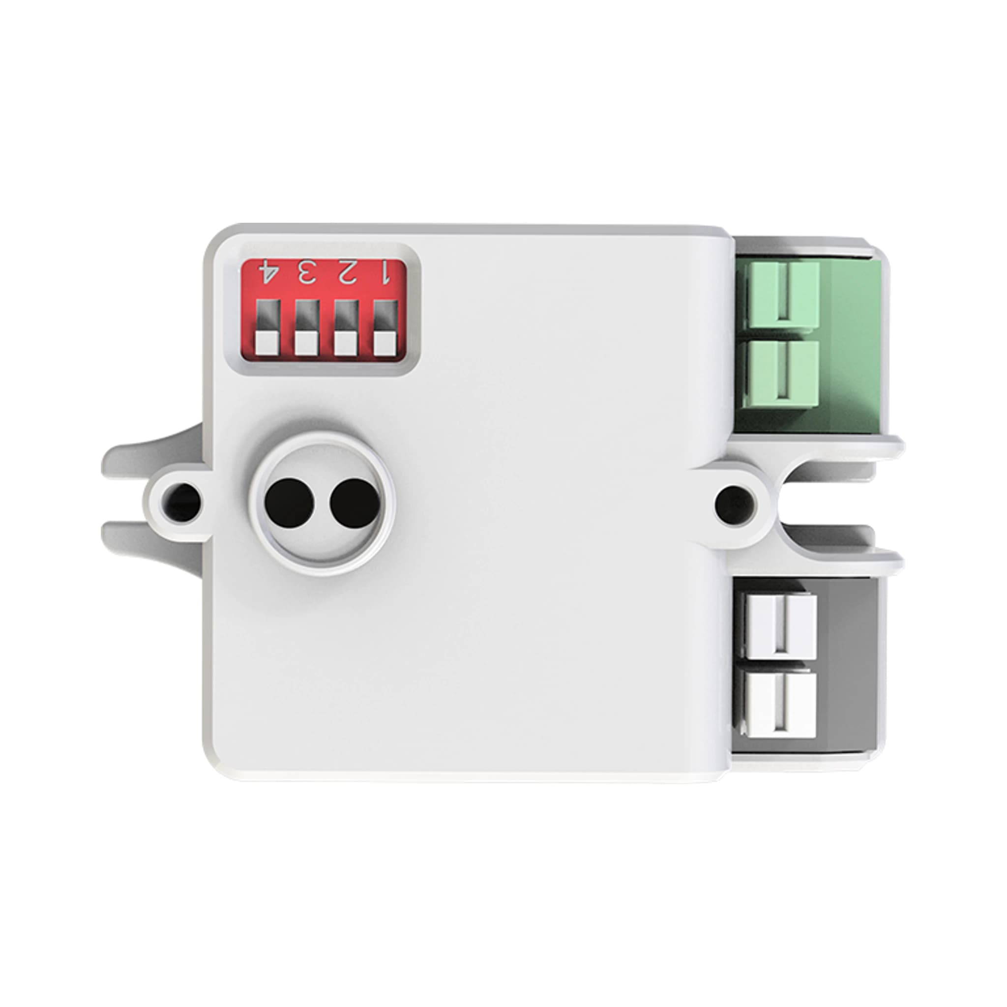 Daylight SensorsMS02View full product parameters
- Operating voltage
- 187-264VAC, 50Hz
- Rated input voltage
- 220-240VAC, 50Hz
- No-load power
- <0.5W
- Maximum load
- <400W capacitive/LED; <800W resistive
- Output
- ON/OFF
- ON / OFF threshold pairs
- 5/25, 10/50, 25/75, 50/100, 100/200, 150/300, 200/400Lux; Disable
- Operating temperature
- -25 to +60 C
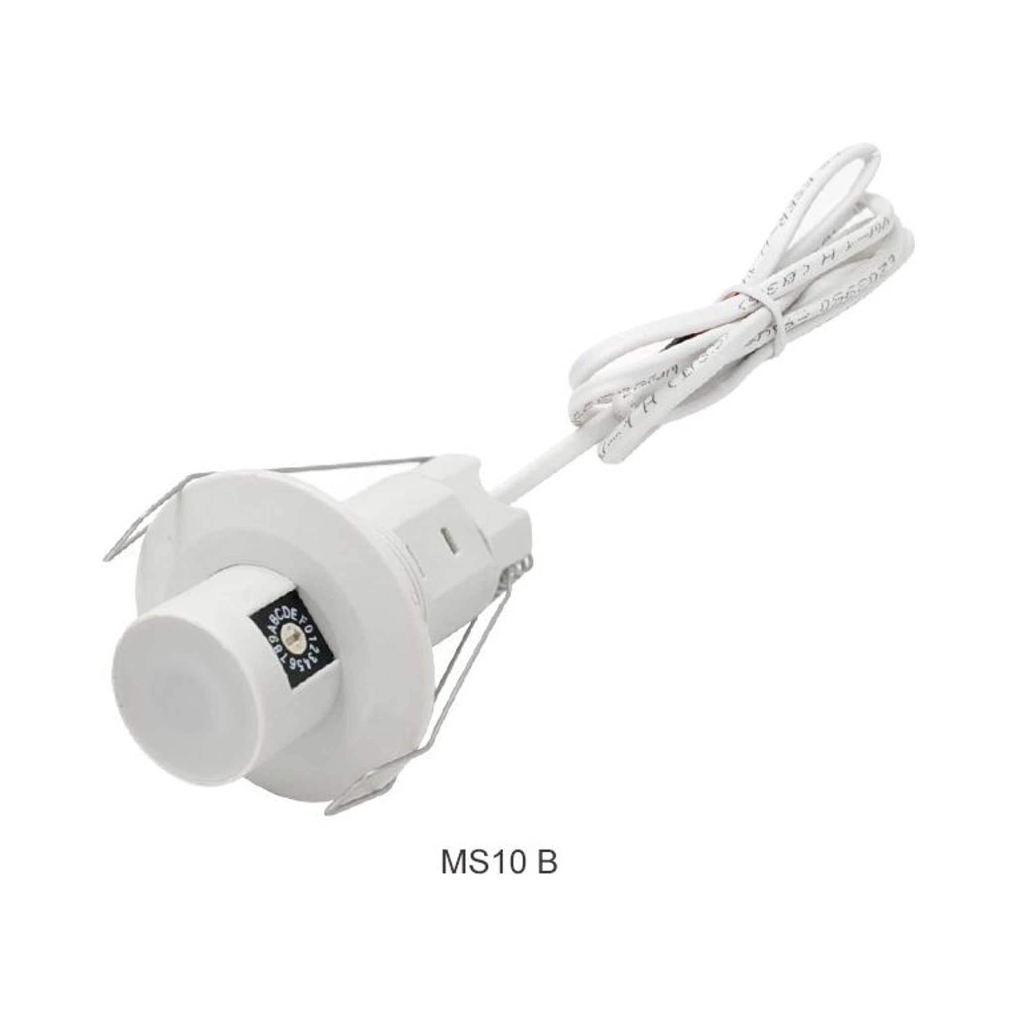 Daylight Sensorsconstant-light controllerMS10View full product parameters
- Models
- MS10 A / MS10 B
- Rated voltage
- 1-10V DC
- Output signal
- 1-10V DC dimming
- Working current
- <50mA, non-constant-current source
- Function
- Constant-light daylight harvesting
- IP rating
- IP20
- Networking
- N/A
References and editorial note
Sources were reviewed on 2026-09-07. Recent industry sources and basic technical references are listed separately. The article is original engineering commentary grounded in the current product record, not a translation of the cited source. Any calculation or recommendation does not represent completed product interoperability testing.